Difference between RF isolator and RF circulator
In practical applications, RF isolators and RF circulators are often lifted at the same time. How is the RF isolator and RF circulator connected? What's the difference? This article will focus on these issues. The RF isolator, also known as the one-way device, is a device that transmits electromagnetic waves in one direction. When the electromagnetic wave is transmitted in the forward direction, all the power can be fed to the load, and the reflected wave from the load is greatly attenuated. The unidirectional transmission feature can be used to isolate the effects of load changes on the signal source. The RF circulator is a branch transmission system with non-reciprocal characteristics. The commonly used ferrite RF circulator is a Y-junction RF circulator, which is composed of three branch lines symmetrically distributed at an angle of 120°. .
1. What is an RF isolator?
The RF isolator, also known as the one-way device, is a device that transmits electromagnetic waves in one direction. When the electromagnetic wave is transmitted in the forward direction, all the power can be fed to the load, and the reflected wave from the load is greatly attenuated. The unidirectional transmission feature can be used to isolate the effects of load changes on the signal source. Taking the field shift isolator as an example, the working principle of the ferrite RF isolator is further described.
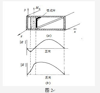
Field-shifting isolators are made based on the effect of ferrite on the field shifts produced by the modes transmitted in both directions. It adds an attenuator to the side of the ferrite sheet. Because the deviation of the field generated by the two directions is different, the electric field of the transmitted wave in the forward direction (-z direction) is biased toward the side without the attenuator, and in the opposite direction ( In the +z direction, the electric field of the transmitted wave is biased to one side of the attenuator, thereby achieving an isolation function with a small positive attenuation and a large reverse attenuation, as shown in FIG.
Second, what is the RF circulator?
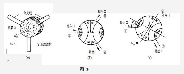
The RF circulator is a branch transmission system with non-reciprocal characteristics. The commonly used ferrite RF circulator is a Y-junction RF circulator. As shown in Fig. 3(a), it is composed of three mutually 120°. The angularly symmetrically distributed branch lines are formed. When the applied magnetic field is zero, the ferrite is not magnetized, so the magnetic properties in all directions are the same. When the signal is input from the branch line "1", the magnetic field shown in Fig. 3(b) is excited on the ferrite junction. Since the conditions of the branches "2, 3" are the same, the signal is equally divided. When a suitable magnetic field is applied, the ferrite magnetizes, and due to the anisotropy, the electromagnetic field shown in Fig. 3(c) is excited on the ferrite junction, and when a suitable magnetic field is applied, the ferrite is magnetized due to The effect of anisotropy is that there is a signal output at branch "2", and the electric field at branch "3" is zero, with no signal output. When the branch "2" is also input, the branch "3" has an output, and the branch "1" has no output; when the branch "3" is input, the branch "1" has an output and the branch "2" has no output. It can be seen that it constitutes a unidirectional circular circulation of "1" → "2" → "3" → "1", and the reverse direction is impassable, so it is called a radio frequency circulator.
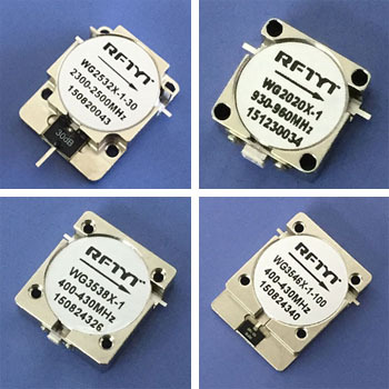
The picture above shows the RF embedded isolator
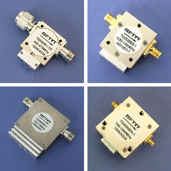
The figure above shows the RF coaxial isolator
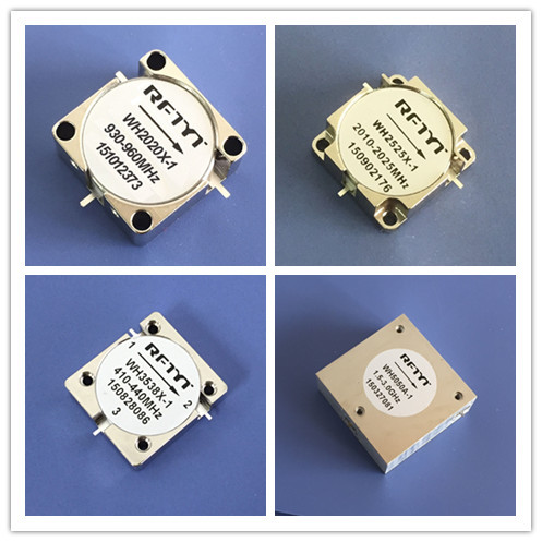
The figure above shows the RF embedded circulator
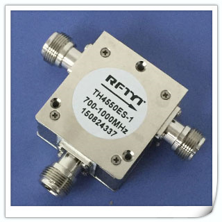
The figure above shows the RF coaxial circulator
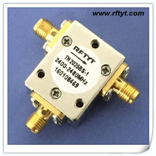
The figure above shows the RF coaxial circulator
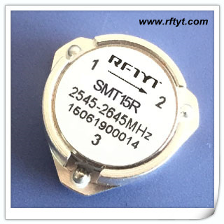
RF surface mount isolator (SMT isolator)


